Use an linear position sensor to move an object on the screen
This application note will give an example that describes how to use a linear position sensor to manipulate an object on the screen. We will take a brief look at:
- the components required and where to get them
- how to configure the hardware
- how to wire up the components
- how we configure blocks to connect to the components
- how to build a block that is manipulated by the input from the sensor
The hardware
In this example we will use a draw wire encoder, this is basically a tape measure style encoder that is a quadrature encoder with retractable wire attached to it. We will also need something to interpret the pulses from the encoder and track any moments into a counter. This can be done in many ways but one way that is straight forward in Blocks is to use a Modbus enabled device. In this case we should consider a device that is fast enough to be able to track the pulses from the encoder. The encoder in this example gives out about 2000 pulses per revolution and on the wire that is about one pulse per 25 μm, so moving the wire swiftly will put the counter to a test.
Draw wire encoder
RLC63D-2500-D1F-1M Draw Wire Sensor made by China Rongde Optics Co Ltd.
We found this reasonable priced draw wire encoder that can be bought from Phidgets.com. This particular one come in different lengths between 0,6 up to 2,5 meters. Any quadrature encoder should work but this application note is using this model.
DAQ (data acquisition system)
LabJack T4 made by LabJack Corporation.
This is yet another reasonable priced device typically used for prototyping and general data acquisition. Since it is very fast and has built in Modbus support it can be useful for many Blocks projects. They are available from many distributors globally. We bought ours from here. This device can also be used as a Digital and Analog I/O device just like general Modbus I/O devices.
Set up the LabJack T4 DAQ
Install the software
The device set up is made in the Kipling software available for Windows, MacOS and Linux. All the software installers suits can be downloaded from LabJacks website. Follow the installation instructions provided by LabJack. Connect the LabJack T4 to the computer with Kipling installed with the USB cable that came with the device. The USB provides enough power to drive the device.
Open the Kipling software.
You should see something like this screenshot and Kipling should have found you device with a green button labled USB.
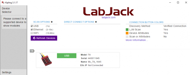
Klick the USB button to connect KIipling to the device.
Familiar yourself with the device
By following this Quick Start tutorial you can try some of the features of the device before setting it up for Blocks.
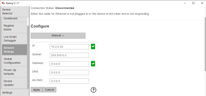
Configure the Ethernet
Select the Network settings from the left side menu. Configure the network so it is within your subnet. In my case this is 10.2.0.20. You will have to set details that match your own network topology.
Update the firmware
We should update the firmware on the device. Firmware files and more detailed support for firmware installation can be found here. At time of writing this note I will use the beta version 1.0027 as that version has a fix that enables Modbus to receive overlapping requests from multiple clients. If running on lower firmware you should limit yourself to just communicate to one single Modbus register.
Configure a quadrature input
In this step we will configure the FIO6 andFIO7 lines for quadrature in. Keep in mind that only adjacent even/odd pairs of FIO lines may be used for quadrature in.
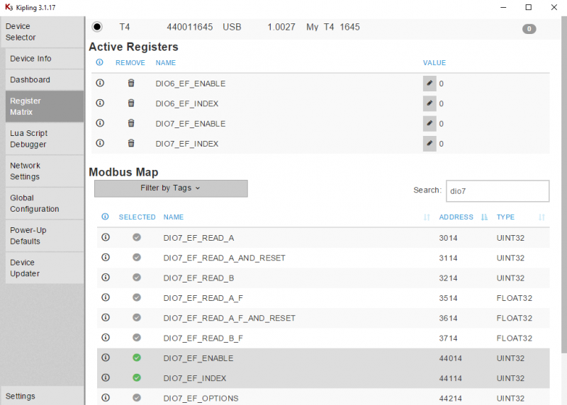
In Kipling, select the Register Matrix from the left menu. Use the search field to find the registers and make select and make them active by ticking the little circular checkboxes.
You should see something like this:
Set the following registers in this exact sequence:
First, disable the Extended Features:
DIO6_EF_ENABLE = 0    //Make sure DIO-EF is disabled on DIO6 before changing the EF_INDEX
DIO7_EF_ENABLE = 0    //Make sure DIO-EF is disabled on DIO7 before changing the EF_INDEX
Second, set the Extended Feature to quadrature in:
DIO6_EF_INDEX = 10    //Set feature index for DIO6 to quadrature.
DIO7_EF_INDEX = 10    //Set feature index for DIO7 to quadrature.
Finally, enable the Extended Features again:
DIO6_EF_ENABLE = 1    //Enable quadrature DIO-EF on DIO6, for A phase.
DIO7_EF_ENABLE = 1    //Enable quadrature DIO-EF on DIO7, for B phase.
You should have these settings when done.

Keep the Kipling register matrix in mind, this is the best place to lookup the modbus registers address. For even more details, read the LabJack quadrature in documentation here.
Configure the power up default settings and values
The last but not least important step in preparing the LabJack is to make sure we don't have to do this setup avery time we reboot the device. Click the Power-Up defaults in the left menu of Kipling.
You should see something like this:
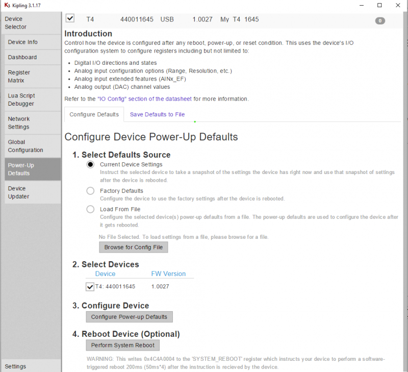
Select Current Device Settings as Defaults source. Select your device from the device list. Configure the device snapshot by clicking the Configure Power-up Defaults button. Reebot the device
Connect the wires
The encoder has five different leads coming out of it, attach them to the LabJack's screw terminals FIO6 and FIO7, configured for quadrature in following this table:
| LabJack terminal | LabJack function | Encoder Cable Colour | Encoder function |
|---|---|---|---|
| FIO7 | DIO07_EF B phase | Green | Data (B) |
| FIO6 | DIO06_EF A phase | White | Data (A) |
| GND | GND | Black | Ground |
| VS | 5V | Red | +5V |
| N/A | N/A | Yellow | Z-Index |
In this setup we don’t use the Z-index feature. Z-index is a separate pulse that is high once per revolution and this van be used by the counter to detect if it slips due to high speed on the encodes. That feature can reduce the error if that would happen.
You should now be able to test the encoder and the counter. Open Kipling and the Register Matrix. Make the DIO6_EF_READ_A_F register active and see if the counter. If not, revisit the previous steps until it does.
Finally, plug in the LabJack module to your ethernet switch.
Configuration in Blocks
Start Blocks
You need a computer with a running blocks server and a web browser.
We have prepared a PIXILAB-blocks-root folder containing everything you need to run the examples. Download this ZIP file and unpack it If you don't know how to do this, read the instructions in the general setup section.
If you have done the general setup, copied the files and pointed to this application notes root block, follow the next steps to run this application on your computer.
- Start Blocks.
- Open the editor using the Admin button.
- Log in using the name admin and the password pixi.
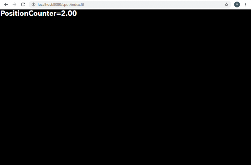
- Open http://localhost:8080/spot/index.ftl in a second browser window. If not, you may have to reassign the Display spot.
Configure the Modbus module in Blocks
Now go to the editor and the Manage page, Select Modbus I/O Modules.
You should have a module already configures like this:
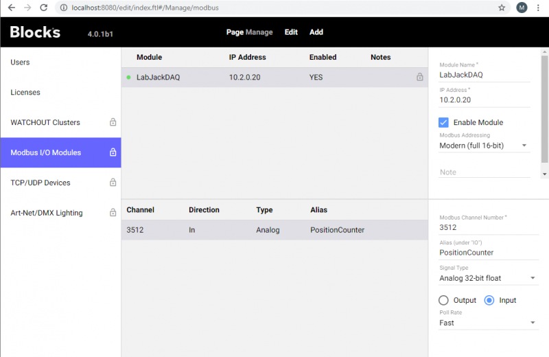
If you use a different IP setting from this guide, please edit the IP address settings for your module. Make sure the module is connected by looking at the indicator, it should now be green. As you can see from the I/O channel configuration we will be polling Modbus channel 3512, I have given the I/O channel a friendly name and we use the data type Analog 32-bit float.
As you can see this I/O channel uses the fast polling setting. This is a typical application where this should be used. Never use that setting unless needed as that may create a lot of excess network traffic and essentially is a waste of resource.
If you look up the DIO6_EF_READ_A_F (our counters register) in Kipling you should find that the address is 3512 it is read-only and the datatype is FLOAT32.
Run the sample
If you go back to the spot browser window you should now be able to use the wire-encoder to change the PositionCounter value and move an object downwards from top of the screen, like a curtain. If the number doesn't change, open Kipling and the RegisterMatrix. Make the DIO6_EF_READ_A_F active and see if the counter still works
The block explained
Type CTRL+1 or click the Blocks logo shortcut in the editor to get to the Display page. Edit the LinearPositionIndex block and examine the content.
The text block has a binding to IO/PositionCounter, {$1} show the value of the counter.
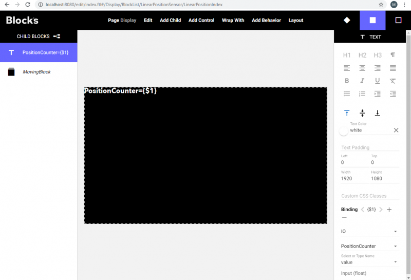
The MovingBlock is just a 1920x1080px composition with a red background and is positioned at top -1090px, that is just outside the visible area of the screen.
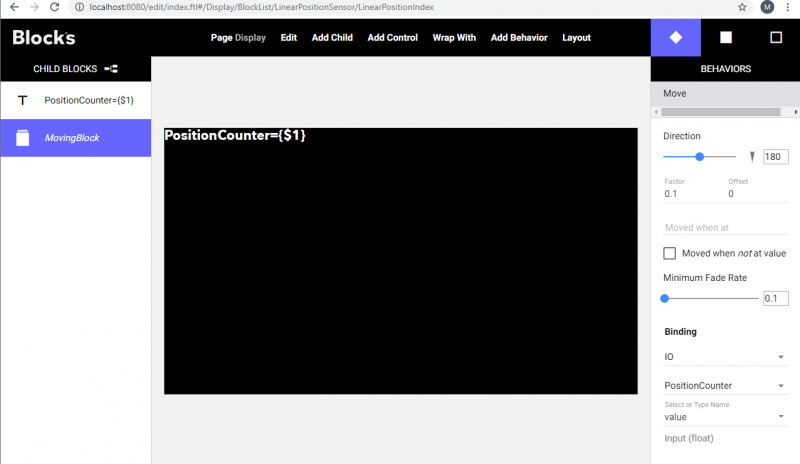
It has a Move behavior applied to it, select the block and click the diamond shaped icon to see its behaviors.
We use a factor of 0.1 to move it a bit slower andf we added a very short minimum fade rate, just to smoothen the movements.
Examine the settings and try to manipulate the factor and minimum fade rate of the behavior.
Play around
Feel free to play around and create other blocks with different behaviors. Bind the behaviors to the PositionCounter. Different behaviors may require different factors and offsets to behave as you want. You may also want to try to apply multiple behaviors and bind them all to the PositionCounter. Also try with some of your own more exiting content like images and videos in your block.