Table of Contents
Control a Siemens LOGO! PLC with modbus
Introduction
This application note describes the steps to configure the device and blocks to be able to set the coils and read inputs of the device. Device version LOGO!8.3 is used in this example, but it is likely to work for any model of the Siemens LOGO! PLC. It is possible to buy a get started kit that contains a device and the configuration software in one single kit.
This application makes use of recent Blocks modbus implementation enhancements so make sure to use Blocks 6.3.1 or more recent.
A few of the benefits of this type of device is:
- Good value for money
- Can be extended with additional modules.
- Fits in a standard DIN 43880 enclosure fixed with a DIN EN 50022 35mm rail.
- Electricians will be happy to install them in any mains system.
- Can be programmed for special tasks from programming the PLC (not within the scope of this tutorial)
Set up the device
Follow the vendors documentation in how to set up IP address of the device. On devices with display that can be done from the device buttons using the built in menus.
Make sure you have the vendor software LOGO!Soft Comfort installed on a PC.
Enable modbus on the device
- Open the LOGO!Soft program.
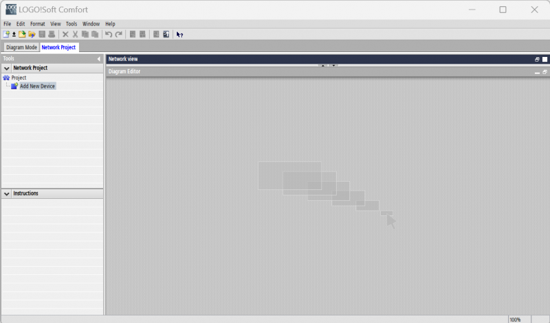
- Create a new network project from /file/new
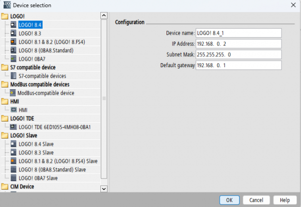
- Click Add New Device from the Tools menu to the left.
- Select the device model that you intend to use from the list to the left.
- Enable the communication between the software and the device by specifying the ip of the device.
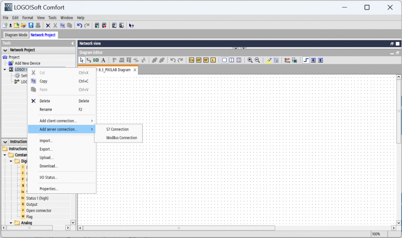
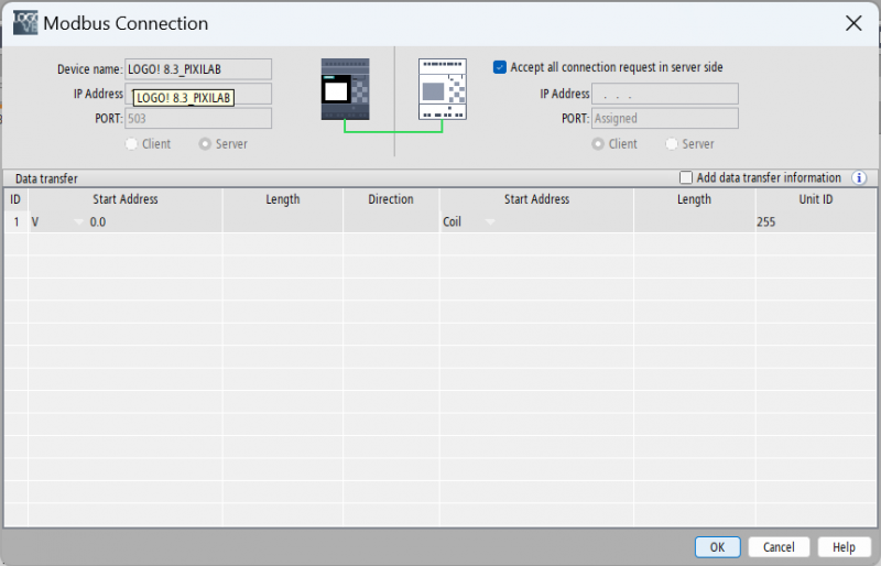
- Rightclick on the device and select /Add server connection/Modbus connection/
Here it is possible to specify connections from a perticular server/servers. In this example i will leave it to accept all connection requests server side.
Now that we have done that we are ready to upload the configuration/program to the device.
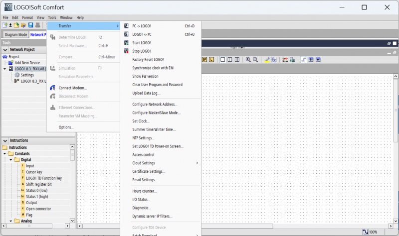
- Click Tools/Transfer/PC→LOGO! or ctrl+d to upload.
That is it, the device is now prepared for modbus control.
Configure the device in Blocks
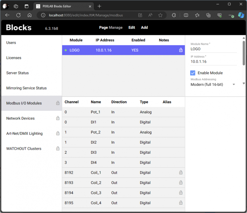
In Blocks one add any modbus register that one wish to control/read as separate modbus channels. This is done from the manage page and the Modbus I/O modules tab.
As soon as we got that setup we can use all channels as properties in Blocks allowing us to bind controls or texts to display or control the property values..
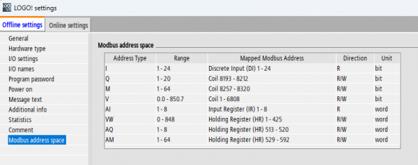
Modbus address space of the LOGO! device
The modbus address space is documented in the device settings found by double clicking settings under the device in the tools menu of the LOGO!Soft comfort programming software, then select the modbus address space tab.
Temporary limitations
Currently (Blocks version 6.3) it is not possible to read holding registers with modern addressing. We added a feature request to add the ability to manually set the modbus function per channel. Currently this is decided automatically based on the data type and direction. To work around this, one can use the classic modicon addressing and translate the Siemens addresses documented in standard modbus address style (modern) to modicon.
In example: Since the modicon addressing is not 0 based we end up with: coils 8193-8196 and so on. Addresses starting with 3XXXXX will use function 4 (input registers) Addresses starting with 4XXXXX will use function 3 (holding registers)
In this blocks configuration I added the same as in the example above, but I also added a holding register. I wanted to read that because I programmed a pulse counter in the PLC that outputs to the holding register. This way I can expose the value as a property in blocks and make use of it in any task logic or expose it in content.
![]()
Programming the PLC
It is not that hard to program a PLC, please use online tutorials and Siemens documentation regarding how to create programs.
